Tapeout
To submit your design, you need to fill out a Tapeout Spreadsheet that was provided by MUSE. There are six sheets provided:
- Specification
- Trial
- Final
- Contact
- Export
- Shipping
Ensure that all sheets except "Final" are filled out before the Trial submission deadline. The "Final" sheet should be filled out before the Final submission deadline.
Trial submission
In the Tapeout Spreadsheet, the following Trial handoff requirements are given:
- Layers: All layers used in the final database are present in Trial.
- GDS: Required to be hierarchical, not flat
- DRC: TSMC requires executing all DRC command files with latest version. For each command file, upload only the "drc.summary" log file.
- DRC: DRC waiver requests are not required for Trial. Please complete the DRC Waiver Request Presentation if you would like Muse to advise on the waivability of a DRC violation prior to Final.
Submit the following materials before the Trial submission deadline:
- GDS and DRC summary files
- DRC Waiver Request Presentation
- DRC summary file SHA 1 checksum
- Verify that the latest version of the DRC files were used
The checksum can be found by navigating to ~/Cadence/DRC in terminal and typing the command sha1sum <filename> or shasum <filename>.
Final submission
In the Tapeout Spreadsheet, the following Final handoff requirements are given:
- Fill: OD/Poly/Metal fill included in GDS.
- DRC: TSMC requires running all DRC command files with latest versions. For each command file, upload only the "drc.summary" log file.
- DRC: TSMC requires each DRC violation in the "drc.summary" log files to be documented in the DRC Waiver Request Presentation.
- Package: If Muse is managing assembly, the package bonding diagram is required to be uploaded.
Submit the following materials before the Final submission deadline:
- GDS and DRC summary files
- DRC Waiver Request Presentation
- DRC summary file SHA 1 checksum
- Verify that the latest version of the DRC files were used
- Bonding diagram
The bonding diagram can be emailed to a representative at Muse.
Wirebonding diagram
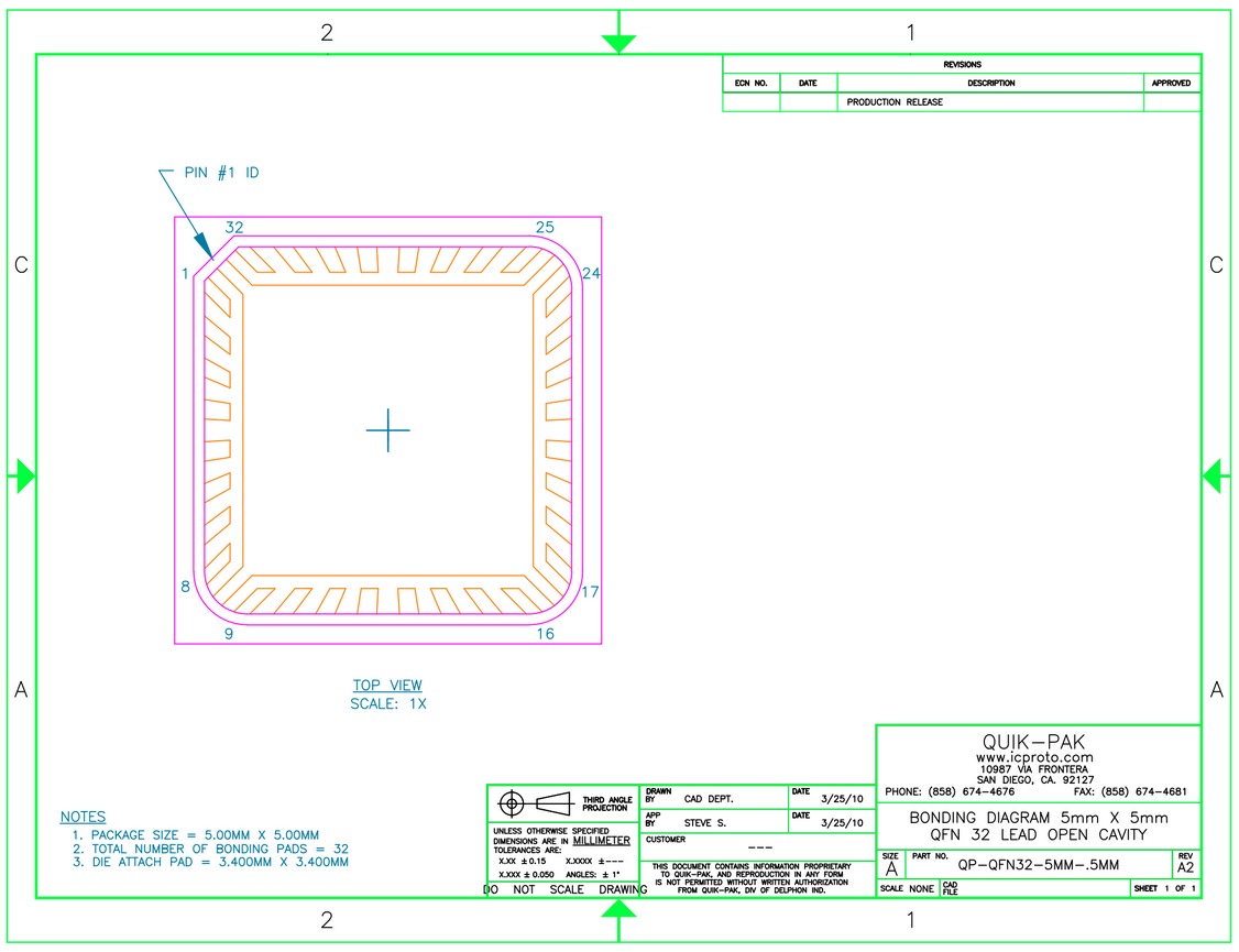
In the Tapeout Spreadsheet in the "Specification" sheet, click on the link for "Bonding Diagram." You will be directed to a bonding diagram provided by QPT in DropBox. Take a screenshot and insert it into a PowerPoint presentation. The following image shows the image included in DropBox:
In the ASIC_Tapeout layout, click "NV" to turn off visibility of displayed layers. You want to select a few layers that show the pads and chip orientation clearly with vibrant colors on a white background. For the ERASICv1, a rectangle in the DNW layer was added to denote the border of the chip, and the layers M6, CB, CB2, ref, and DNW were made visible.
Navigate to File → Export Image. Under "Appearance," click "Swap" so that the background is white. Under "Output," select a name and location and save the image.
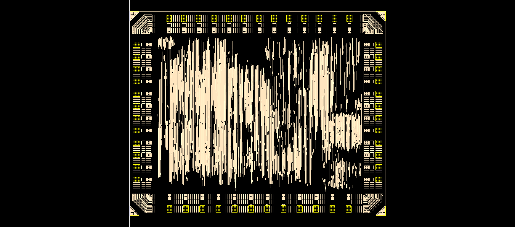
You may need to play around with the layer colors so that they have high contrast with the white background. For the ERASICv1, the selected layers were pale in comparison to the black background, so the image was exported with a black background, then the colors were inverted for the bonding diagram. The following image shows what was exported from Cadence:
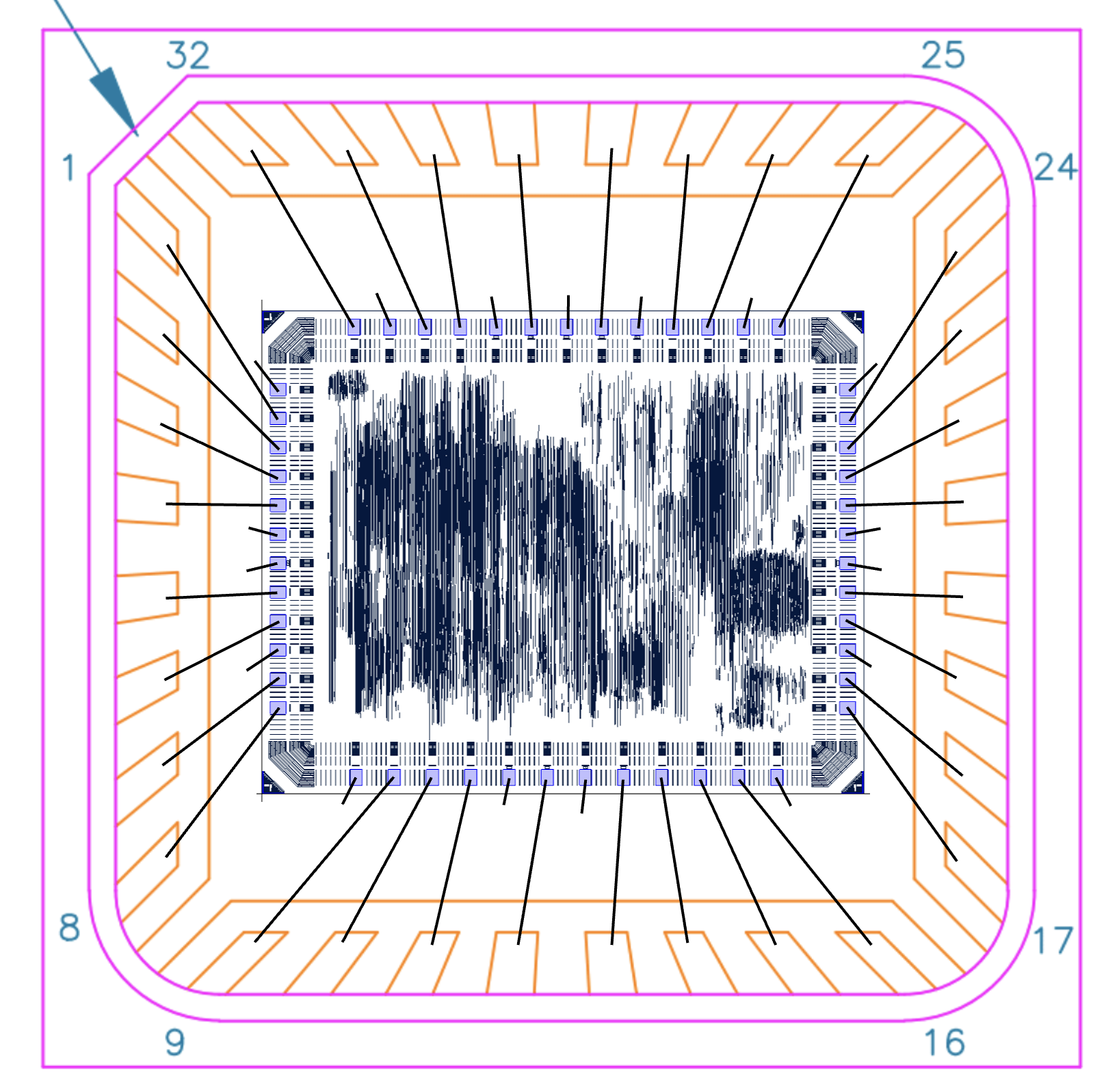
Insert the layout image into the PowerPoint presentation. Add lines that connect all the pads to their corresponding pins. VSS and VSSPST can connect to the substrate. The following image shows the wirebonding diagram submitted for the ERASICv1: